
Ever since moving into my current apartment, I’ve been frustrated that the radiator does not have an easy way to control it, especially the one in my office with its position under an almost-permanently-closed cabinet that I usually store a large pile of stuff on top of. I’d like to continue using that cabinet to hold stuff, and avoid manually messing with a radiator, without getting roasted alive in my office or having to bundle up when it’s too cold. Here is my first attempt at that– please leave helpful comments if you’d like (they are appreciated)! I’d like to do something similar for the bedroom, but it would need to be quieter than this. I’d also like the mounting adapter for the handle to be less janky.
Final Result

Phase 1: Electronic Design
To understand how I might accomplish what I wanted to, I put together some parts on a proto-board. I threw that away before deciding to make a blog post– otherwise, I would post a picture here. Needless to say, it was very messy. By the time I had something with the functionality I needed, it would stop working if I looked at it funny. Since I didn’t want to bury something like that in my wooden radiator cabinet, I decided to have a PCB made.
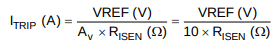
Originally, I had gone with a resistance of 0.25 Ohm for the current limiting in the H-bridge chip, but I found that this let the motor to use too much force when attempting to close an already-closed radiator valve, stressing the design and potentially damaging the radiator. 1 Ohm was not enough force, and 0.5 Ohm as shown below is probably slightly too much, but this worked well enough. I noticed that my specific motor had a voltage drop of 0.025 V across the sense pins when the resistor bank was fully populated, giving me an unburdened current of ~100mA.
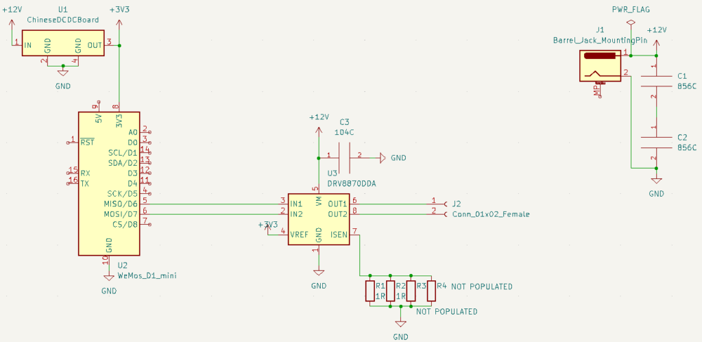
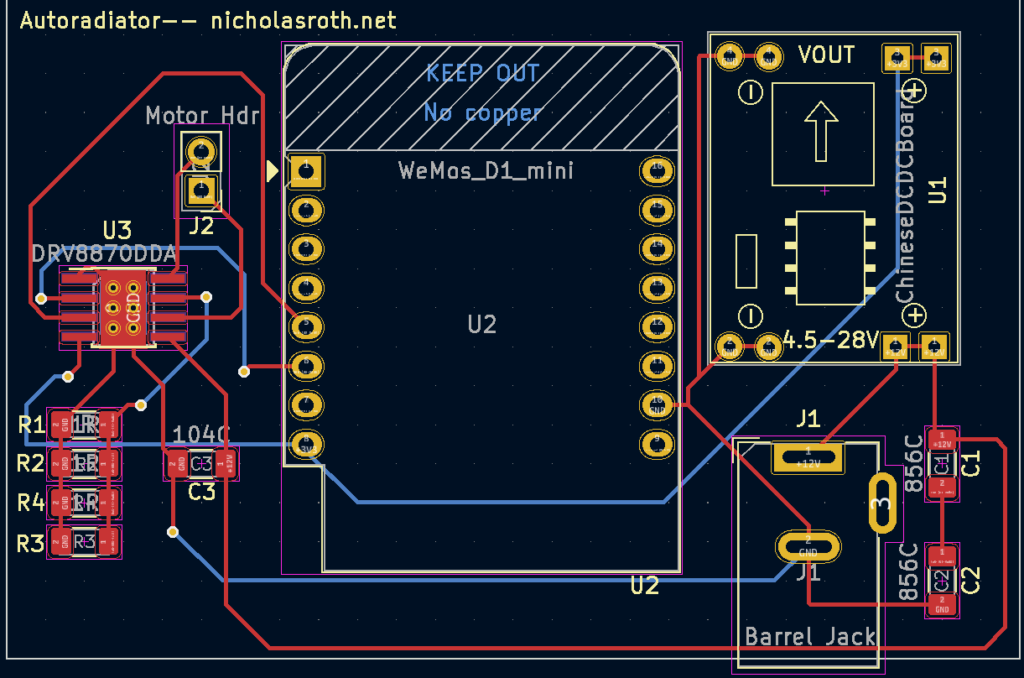
Design + Parts Notes
PCB Design: KiCAD files at https://github.com/rothn/autoradiator/tree/main/pcb/autoradiator.
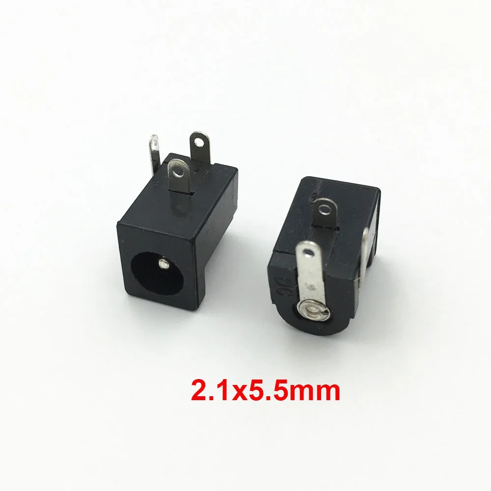
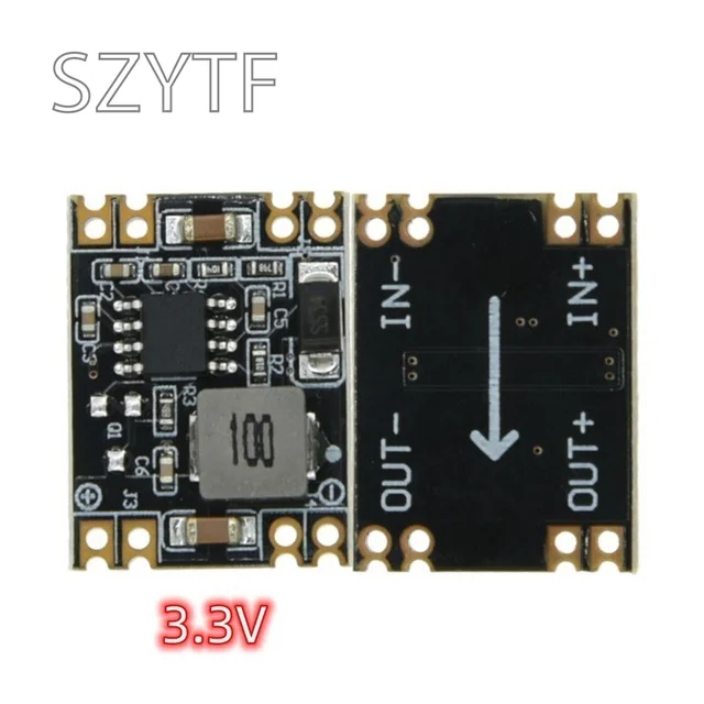
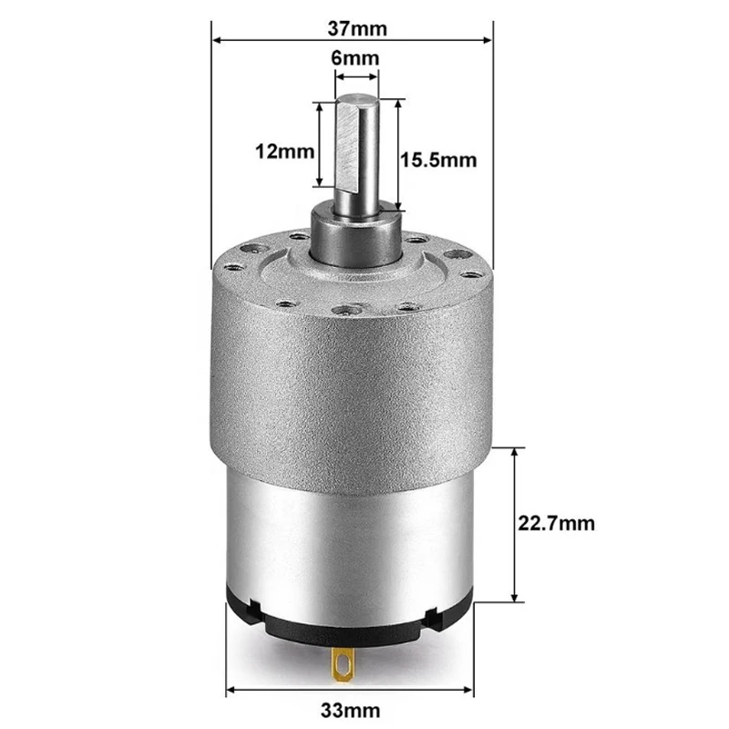
I couldn’t find a serial number for the DC-DC daughterboard or the barrel jack, but both appear to be fairly common on Aliexpress. I would prefer to buy locally, but NYC does not appear to have local electronics stores that carry components like these. I used the 5.5×2.1mm barrel jack at https://www.aliexpress.us/item/2251832639482979.html and the DC-DC board at https://www.aliexpress.us/item/3256805140456802.html. The motor is a 7RPM, 12V JGB37-520, available at https://www.aliexpress.us/item/3256803087419738.html. To use a different voltage motor (below 26V, the limit of the DC-DC board), just be sure to use the appropriate power supply. Note also that the barrel jack here is wired for center-positive power– be sure to test with a multimeter prior to populating the rest of the board if unsure about the power adapter. I used https://www.amazon.com/dp/B00FEOB4EI, and it worked well.
I flashed the D1 mini board with ESPHome before soldering it into the board.
Process
Before populating the circuit board, I flashed ESPHome onto the D1 mini board through its microUSB connector. The footprint of the board doesn’t allow me to plug this in after installing it, so I made sure to check that this connected to wi-fi properly before moving on. My configuration includes a device-hosted recovery wi-fi network for re-flashing the device and updating wi-fi settings if something goes wrong. Config: https://github.com/rothn/autoradiator/blob/main/esphome_config/autoradiator-1.yaml
This is what the PCB looked like after populating it with a soldering iron. I added an LM35 temperature sensor since the D1 mini board has an ADC, and that seemed like a useful feature for a radiator controller to have.
Phase 2: Mechanical Design
Since starting the project, I had been wondering how to connect the motor to the radiator knob, which I measured at about 60mm in diameter. I had been planning to build a box to fit the knob, lined with rubber for grip, and attach it to the motor with a flange. I modeled this in FreeCAD to help visualize the wood cuts I’d need and how they’d fit together. The end result was much messier than this, and I’d love constructive comments (below) on how to do this better next time, since I’m planning to build another of these for a different room. To make sure that the knob turned instead of the motor and PCB, I would mount the motor to another board which I’d wedge up against the wall for stability. In the other room, which has the valve in a different orientation, I’ll wedge this board against the floor instead and mount everything sideways.

FreeCAD File: https://github.com/rothn/autoradiator/tree/main/mounting
Design + Parts Notes
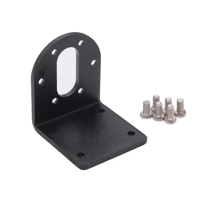
Flanges for these motors are plentiful. I made sure to get a flange that supports a 6mm shaft. I got the flanges pictured here from https://www.aliexpress.us/item/3256802253656337.html. For the wood, I got some MDX from a local hardware store, and some sheet metal screws to fasten it all together. In the end, I also used M3 metric screws to attach the flanges to the motor mounting adapter for the radiator knob, since these flanges are threaded with that type of thread. To enhance the grip on the mount, I used 1mm-thick adhesive rubber pads from https://www.aliexpress.us/item/2251832842955384.html. The mounting bracket comes from https://www.aliexpress.us/item/3256803783515065.html.

Process
This wood is MDX, so it was important to drill pilot holes first to keep the boards from splitting, especially when I drilled in from the side (between layers).
After building a lopsided box, I realized I would need to find the center of rotation, or the motor wouldn’t be able to fully rotate the valve. I did so by drawing a spiral with my pencil while rotating the mount on the radiator knob.
I attached the flange at the center with some very weak screws that were too short. The heads broke off, and the flange came off too after some light use. Note that this particular flange was also threaded for M3 screws, and I just figured I’d cut my own threads through those. Not a great idea.
Ultimately, I picked up some proper 20mm M3 screws, drilled pilot holes that were slightly too small, and secured the flange to the wood with those. They were still just slightly too short to go through the wood and secure with bolts as I had originally planned, but I’m not seeing any issues so far.
It turned out that the mounting brackets I ordered were too long and would not clear the mount, so it would not be able to turn without some modification.
Fortunately, the mounting bracket appeared to be made from aluminum, so I was just able to score this with my drill and then break it on the side of my desk/workbench. Safety glasses are very important for the drilling step!
A quick test showed that this was able to clear the radiator-gripping box, while still leaving me two screw holes to mount a board to anchor the motor to a wall and keep it from spinning.
Here, I took measurements for the anchor board. It’s best if it fits snugly.

Marking holes to screw the anchor board in…
After everything looked good, I tightened the motor shaft into the flange.
Then, I installed the device on my radiator knob with tape so that the wires would not get caught when the knob rotates.
Next Steps
The current design is very janky. For example, just look at how it wobbles when it rotates in the video. I’d like to make this less janky, but I’m not sure where to start. A couple of things I’d like to see would be:
- Adjustable grip, so that I can adapt to a different size when I move and also ideally sell this as a kit to my neighbors
- Address the wobbling, perhaps by using 3D-printing (though I’m not sure PLA could handle the torque from solidly turning the radiator valve).
Please leave comments with suggestions!
Leave a Reply